Last time around I ran into two major issues.
- Tolerance between moving parts was too tight. My pivot pins on the inner ring were pretty much jammed into their holes…
- Fragility of the part. Using 1mm diameter pivot pins using the detail material (weak) was not a good idea. Coupled with the tight pin problem above, it meant I accidentally snapped a couple of pivot pins off the blades when I tried to rotate close the iris.
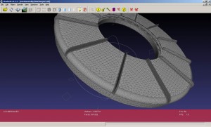
- Coarse triangulation of the exported STL which made the two rings too ‘blocky’ to rotate freely with each another. My fault, fixed by (labourously) tweaking/experimenting with Alibre’s Export.
So how did I fix it all?
The design
This message thread on the Shapeways forums details a few experiments other people have tried printing ‘living hinges’ and moving parts direct from 3D print. Appears the magic number is >0.1mm gap between two components to avoid them fusing together…so I went for a margin of error and aimed for >0.25mm gap.
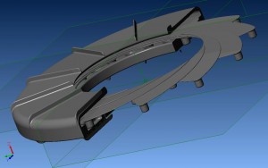
While reading it all, my previous design came as 26 individual components…which probably annoyed the hell out of Shapeways staff while shipping it. With the improved tolerances, I tweaked the design to combine all components into one assembly to be printed in one go hoping it’ll work ‘out of the box’. Yes thats right, printing in ‘one-piece’ and hoping it works!
A few other tweaks here and there; making it smaller to save cost, making the pivot pins thicker, putting a covering skin on it to hide/contain the blades and around an hour later…

One thing to note is that this only took an hour because I cheated and reused my previous Alibre Design files. Being a parametric modeller, all I had to do in most instances is edit some dimension values on the sketches I’ve set up on the previous design. Easy!
I also didn’t bother doing math calculating on how long the sliding slot should be, simply judged it by eye by sliding/rotating the blades in assembly mode to see approximately how much movement I’ll need to achieve full closure/opening. This is seeming more and more like an Alibre advertisement isn’t it?
The painful STL export again…
One rant though is with the STL export – its non-intuitive, the help file instructions were that helpful and it all came down to trial and error. I learnt :-
- Tweaking the normal deviation setting is a bad call. Making it smaller will result in either a humungous file or Alibre crashing out.
- Tweaking the surfaces setting is too painful. It either had a negligible effect on things or I was simply doing it wrong…
- Tweaking the maximum cell size worked! Well kind of. It basically asks the exporting to enforce a triangle plate size to be smaller than what you specify, so a small value generates alot of triangular cells. This is not optimal because even if you had a large flat triangular sheet that could be very well represented by one large triangle, it’ll now be forced to make it into 893475 triangles…
- Why kind of? Because the Shapeways design validator crashed/errored out of me when I had the cell size too fine (0.1). I had to nudge that back to (0.2) before Shapeways accepted the file.

Naturally I used Meshlabs to validate the triangulation and remove duplicate vertices again. This step is required to allow it to pass Shapeways validation, it also cuts the STL filesize by 80% typically.
Oh I forgot to explain why it was painful. Learning items 1-4 above probably took me oh over 2-3 hours? [Though I still remained productive by fixing my girlfriend’s Nintendo DS…].
Waiting for the shipping again
Actually waiting to find my wallet to click the order button 🙂 Lets see how this turns out!
This is the first time I comment here and I must say that you provide us genuine, and quality information for other bloggers! Great job.
p.s. You have a very good template for your blog. Where have you got it from?
Madox,
Awesome job, big Stargate fan so viewed with great interest.
Design has inspired me to develop a new device for my business, actually would you be interested in doing some design work for us? Your skill set leaves mine for dust on 3D modeling, along with teh rapid prototyping using Shapeways we could get a prototype model going in next to no time. Investors would go nuts!!
Drop me an email if interested.
AJW
So how did this project come out in the end? I’d really be interested to hear if it worked. Also I’m looking for a motorized version of this with a bigger radius. Any chance you might pick up this project again?
I’m trying to make one of these things myself. I’ve downloaded patent pdfs, and have come EXTREMELY close, but, two things are still standing in my way:
–I can’t find any clear information on how this rotating ring works. I think I might have a pretty good idea, but haven’t written my equation yet. I think all I have to do is take my measurement of the angle the blades use and determine the appropriate arc length of the pivot slides.
–I can’t find any information at all on how the leaves mesh together in the middle w/o one of them being completely on top of the others. My blades are just flat.
I drew the blades in AutoCAD and used some high-precision measurements. After some experimentation I determined that I could make it close completely if I had “an equation to get an angle THETA such that the second circle, when rotated around the point P(0,13.5), intersects the point P(0,0). The radii of the two circles are identical, but not r. r=13.5 and is the distance of the axis of rotation from the origin. The radii of the circles are both 10m.”
…
Confused yet? See here: http://i160.photobucket.com/albums/t190/webchameleon/problem_example.gif
That second circle represents the inner side of a diaphragm leaf. Turned out I was right, but couldn’t prove it. I thank CarlB over at CADforums for assistance in developing an equation (something I usually do myself). He came up with this:
“Look at the triangle formed by the 2 13.50 long sides, the base of that triangle has a length of R. Divide that triangle in half to form 2 right triangles. For that right angle:
sin (a/2)=(R/2)/13.5
a/2=arcsin (R/27)”
If I’d just divided that triangle I drew to make two right triangles, this would have been obvious. Thanks, Carl.
My question to you, Madox, if you don’t mind my asking, is how do these things mesh in the center?
Here’s a crude, optimized 3dsMAX model from the drawing:
http://i160.photobucket.com/albums/t190/webchameleon/12-16-20091-48-37PM.png
yes, it’s animated.
http://i160.photobucket.com/albums/t190/webchameleon/12-16-20091-50-14PM.png
Can you share your STL?
I’m a little late to the party, but I recently came across http://iris-calculator.com which does all the designing for you. Maybe it is of some help for your next iris project?
Sir, I am trying to design iris mechanism for 30 mm dia with six blades, can any one suggest how to design blades,pls.